| Category |
Assignment |
Subject |
Computer Science |
| University |
University of Reading |
Module Title |
CE1CIC2 Information and Communication |
| Word Count |
500 Words |
| Assessment Title |
Technical Drawing Project |
| Academic Year |
jULY 2025 |
| Deadline |
14th August 2025 |
CE1CIC2 Aims and Objectives
The goal of this assignment is for you to become skilled in the process of developing a simple but typical set of architectural drawings using a chosen information modelling tool (Autodesk Revit) while recognising that many other similar tools exist for this purpose. The project objective is for you to understand the process of information and parametric modelling of a small building, and extract and represent a set of coordinated building information documentation (plans, sections, elevations, details, etc.) at different scales.
CE1CIC2 Assignment Brief
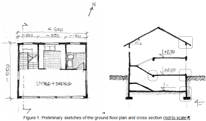
You are a consultant within an engineering firm and have been asked to provide your expertise in designing a two-storey residential house for a client in the Reading area. In your discussions with the client, you agree on the overall design of the house (illustrated in the sketches below) and provide specific recommendations about its orientation, or the way the house should be positioned. You should decide where to locate the home’s windows and the entrance, determine the appropriate floor height, wall and door dimensions, but also design roof overhangs to provide necessary shade in the summer. While the dimensions of the home on the rough sketches below are provisional and can be slightly modified in your detailed design, the following is a list of design parameters for your drawings that you and your client have agreed on:
- The total usable area of the house (basement, ground and first floor plan) should not exceed 150m2
- On the ground floor, the most frequently used rooms (living room and dining room) will face south to take advantage of the sun, while the least used rooms (kitchen, bathroom, and stairs) will be located on the cooler north side.
- On the first floor are two bedrooms and the second bathroom (located above the one on the ground floor);
- The mechanical equipment and other services are located in the basement.
- *The soil on the site is load-bearing (i.e. is compact and can withstand weight) so standard concrete strip footings can be used;
- *Exterior walls are load-bearing cavity walls with a brick exterior, or finish.
- *Interior partitions are made of timber studs.
- *Floor in the basement is an insulated cast-in-place concrete slab
- *Ground floor and first floor are timber frame construction with acoustic insulation
- *The pitch roof is constructed with thermally insulated wood rafters and covered with tiles. The roof slope should be appropriate for the temperate climate.

CE1CIC2 Deliverables:
Based on the information above, create the model of your house using Autodesk Revit and produce a set of the following architectural drawings to send to your client using appropriate scale where applicable:
Cover Page Including the Following:
- Project brief (500 words) describing the project design, including location, actual area, orientation, wall/ floor/ roof construction, materials, and any specific details where applicable.
- References used in developing details and other dimensioning, structural and construction information formatted using Harvard style. If using books, ensure to include the page number(s). If using websites, include the exact page address and date it was accessed
- List of sheets included in the documentation.
- Materials (used in detail views) legend.
- Student ID, module name, project name and date
Plans
- 3 floor plans (basement, ground and first floor) with appropriate room tags and room areas
Elevations
- 4 elevations (south, north, east and west)
Section
- 1 (marked) cross section through the stairs with detail callouts
Details
- 4 annotated details (per Figure 1)
Schedule of Quantities (3)
- 3 tables showing quantities for the following components: 1) room schedule with names and areas, 2) window schedule with the location and size as minimum information, and 3) wall schedule with type and area information as a minimum. Place each of the tables where appropriate.
3D View with the Site
Orthographic or perspective view from the corner of your choice. Ensure that the footings or any other sub-ground elements are not displayed.
Submission Format and Guidelines – Read Carefully!
- The drawings should fit on A3 sheets and adhere to the graphical conventions and rules covered in class. Arrange the views on the sheets as you find fitting, but make sure the layout is clear, legible and logical. No information must cross the sheet borders!
- Choose an appropriate scale for each of the views. Use standard scales (1:100, 1:50, 1:25, 1:10, etc.). Refer to the class notes.
- Make sure all your sheets follow the title block template defined for this class. Refer to the
guidelines provided on BB for Project 1 and the Revit instruction notes “L5 Sheets and Quantities” from the spring term sessions
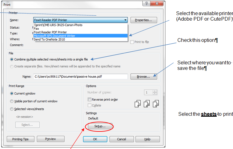
- Save (or “print”) the sheets as a single XPS or PDF file following the steps below. Native Revit files will not be accepted and will automatically receive a mark of 0.
- Submit as a single file to BB named as your studentID.pdf. Check that the correct file is attached before clicking the submit button – you have one attempt to submit. For any Blackboard-related problems with the submission process, contact me or IT-help immediately to avoid late penalties for resubmission.
*To Save Sheets as a PDF or XPS file:
Go to Revit – Print – new window opens:

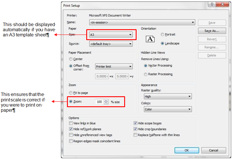
Next, click on “Setup…” and check the following settings as shown in the next image

Click OK and Save your file with your student ID number in the file name
Submission check list
General
- Completeness: All drawing sheets included with specified information at appropriate scale
- File format: Make sure to save in the requested file format – native Revit files will not be accepted
- Brief: proper English, spelling and overall quality of writing
- References: Appropriate, complete and formatted
- Margins and title block: Based on the class template
- Labels and titles: Title for each drawing; room labels on plans.
Graphical representation
- Layout: Clear spacing of the drawings, no crowded or overlapping information, consistent quality
- Annotations: Neat with light/thin leader lines to ensure they are not mistaken for design lines.
- Symbols: North sign for plans, material hatching appropriate and consistent
- Dimensions: Clear and evenly spaced from the drawing, arrows and numbers consistent.
Content integration and model components
- Technical correctness: properly modelled, dimensionally correct and referenced across sheets
- Structural detailing: Appropriate level of detail with annotations and dimensions
- Model components: Proper external and internal walls, footings, basic site, roof connections.
- Stairs: Floor opening, clearances, proper up direction annotation, adequately sized
- Reference and section lines: Appropriate use of section lines and detail callouts as covered in autumn, clean and professional presentation of information


