| Category | Assignment | Subject | Engineering |
|---|---|---|---|
| University | The University of Western Australia | Module Title | GENG2003-ENSC3003 Fluid Mechanics |
| Assignment Due |
Before 23:59 on Monday, May 19th, 2025. |
| Assignment Title |
Pumps & Pipework Systems / Flow in Porous Media
|
| Academic year | 2025 |
1. A centrifugal pump is delivering water at a volumetric flow rate of 250 l/s. During a test, gauges on the suction and discharge flanges of the pump measure (absolute) pressures of 80 kPa and 340 kPa, respectively.
(a) Assuming that the pump suction is the same diameter as the pump discharge, calculate the hydraulic power delivered by the pump.
(b) If the pump efficiency is 76%, calculate the power that must be supplied to the pump (the pump power) to achieve the stated duty (assuming pump suction is the same diameter as the pump discharge)
(c) If the pump suction diameter is 250 mm, and the pump discharge diameter is 200 mm, calculate the hydraulic power (assuming the same flow rate and pressure change)
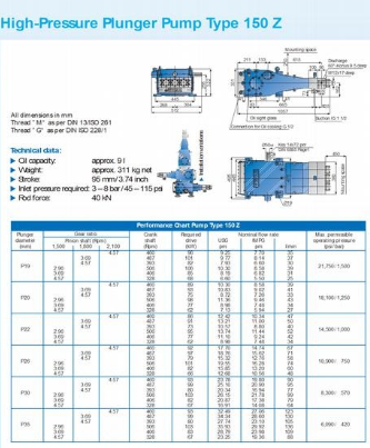
2. A high-pressure plunger pump is used in a cleaning application to deliver water at a volumetric flow rate of 60 litres per minute. The change in pressure across the pump is 750 bar.
(a) Assuming that the pump suction is the same diameter as the pump discharge, calculate the hydraulic power required at the stated duty point.
(b) Which plunger diameter, gear ratio and crankshaft speed would you select from the pump performance chart (provided by WOMA) attached overleaf to achieve this duty?
(c) Given the listed required drive, estimate the efficiency of the plunger pump unit.
(d) It becomes necessary for the flow rate delivered by the pump to be 74 l/min. How would you achieve this?
Submit Your Assignment Questions & Get Plagiarism Free Answers.
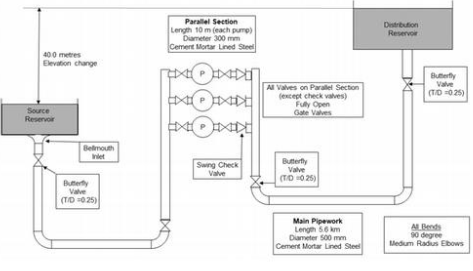
Order Non Plagiarized Assignment3. Water is to be transported from a collection reservoir to a high-level storage reservoir via the pipework system shown below. The pump station is to incorporate three TKL 250 x 300 - 500A ST pumps, arranged in parallel as shown below. The pumps operate in a duty-standby arrangement, such that only two pumps operate at a time (while the other pump sits idle). The design duty flow rate for the system is 400 l/s.
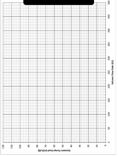
(a) Calculate the system curve, plot it on the blank chart provided - (if this were an exam or assessed question, you would include this curve in your submission). Calculating a minimum of 3 points covering the full chart range will suffice, though you may calculate more if you choose. The mains pipework diameter is 500 mm, and the parallel pipework diameter is 250 mm - you may neglect the straight pipe losses in the parallel section, but not the fitting losses.
(b) Determine the overall duty point for the two pumps operating in parallel to deliver 400 l/s, the individual duty point for each pump, the efficiency at which each pump operates and the required impeller diameter.
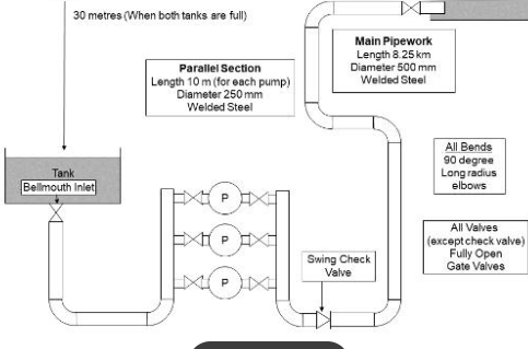
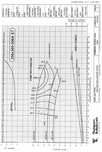
4. Water is transported from one reservoir to another via the pipework system shown below. The source reservoir is located at a lower elevation than the receiving distribution reservoir. The pump station is to incorporate three TKL 250 x 300- 500A Super Titan pumps, arranged in parallel as shown below. The pumps operate in a duty-standby arrangement, such that only two pumps operate at a time (while the other pump sits idle). The design duty flow rate for the system is 420 l/s.
A Moody chart for the friction factor, and tables for pipe roughnesses and fitting loss factors are attached. All pipes are cement mortar lined mild steel. The main pipe diameter is 500 mm, and the pipework in the parallel section is 300 mm in diameter - you may neglect the straight pipe losses in the parallel section, but not the fitting losses.
(50 marks) Calculate OH> for 3 points (flow rates) on the system curve;
. No flow
. Half the duty flow
• The duty flow
From the results, determine
The duty point for each pump
The impeller diameter required to achieve the duty point.
(10 marks) Rather than trimming the impeller to the diameter determined in part (a), one of your team members suggests leaving the impeller diameter at the maximum possible diameter of 520 mm, so that the pump will run for less time over the year to deliver the required total volume of water. Which option (trimming or not trimming) would you recommend, and why?
5. A centrifugal pump draws water at a flow rate of 0.14 m3/s from a tank via the pipework illustrated in the attached figure. At this flow rate, the pump requires a net positive suction head (NPSHR) of 7.2 metres (H2O). The vapour pressure of water at 20˚C is 17.535 mm Hg.
(a) Calculate the NPSHA at the pump. Is cavitation likely?
(b) If cavitation is likely, how would you propose reconfiguring the system to provide sufficient NPSHA to avoid cavitation?
Take our academic assistance & get 100% plagiarism-free papers
Buy Today, Contact Us7. Slow sand filters are used for purification in water treatment plants. In this small plant, inlet water is supplied into a supernatant water reservoir that sits above the sand bed, which is 1.5 m deep (the inlet pipe is above the free surface of the supernatant reservoir, and need not be considered as part of the sand filter system). The water flows through the bed into an underdrainage collection, where it passes to a weir chamber. The flow then passes over the weir, with the free surface at the weir sitting 2.5 m below the free surface of the supernatant reservoir.
The sand filter has a cross-sectional area (perpendicular to the direction of flow) of 8.0 m2. The sand particles in the bed have an average diameter of 0.25 mm, and the void fraction in the bed is 0.37.
Determine the volume flow rate of water through the filter (in m3/day).
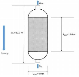
8. A packed bed reactor design is proposed, which uses upward flow through a 12.0 m long bed that is packed with 15.0 mm diameter spherical particles. The diameter of the (cylindrical) bed (perpendicular to the flow) is 4.0 m, and the void fraction in the bed is 0.41.
The pressure head at the inlet to the column (where QIN enters in the diagram below) is 52.0 m (H2O); the pressure head at the outlet (where QOUT exits in the diagram below) is 12 m (H2O). The process fluid has a specific gravity of 0.89 and a viscosity of 0.7 centipoise.
Determine the volume flow rate passing through the bed under these conditions.
Get expert assignment help for GENG2003-ENSC3003 Fluid Mechanics! We specialise in offering high-quality engineering assignment help, with an option for students to pay our experts to take on their assignment challenges. Need a reference? We also provide a free list of assignment examples to help you get started. With years of experience, our writers deliver 100% plagiarism-free content and offer unlimited revisions to meet your needs. Trust us to help you excel in your studies!
Hire Assignment Helper Today!
Let's Book Your Work with Our Expert and Get High-Quality Content
