| Category | Assignment | Subject | Engineering |
|---|---|---|---|
| University | University of Sheffield | Module Title | CPE6280 Instrumented Systems & Functional Safety |
This assignment carries 100 marks.
To complete the assignment, please use the course notes and discussion, references given, plus any other research you deem appropriate. Please justify your statements; justification is as important as being correct.
Please submit your assignment to the CPE6280 "Final" Turnitin submission point, preferably as a Word file.
The filename of your submission must be your student number - module number; e.g. 123456789 - CPE6280
The assignments are marked anonymously; please do not use your name within the assignment. No other identifying marks should be used, including "themes" to personalise your work.
The front page of your submission must have your student number and the unfair means statement.
Your assignment number is: CPE6280 - «Assignment»
The unfair means statement is:
"The attached is all my work except where specifically stated. I have read the section on Plagiarism in the PGT student handbook. I understand it, and the attached work contains no Plagiarism as defined therein."
It is your responsibility to ensure that your submission is in a format that can be marked; once you have submitted to Turnitin, please check this.
It is your responsibility to ensure that your submission is in a format that can be marked; it is therefore recommended that you check this both before and after you have submitted.
There are formal penalties for any assignment submission that significantly exceeds the upper word limit for an assignment. The normal upper word limit is 4,000 words, excluding the front page, table of contents, references, charts, and figures. Penalties start at over 5,000 words. These penalties are in addition to any formal penalty for late submission. Please refer to the PSLP student handbook for further information.
CPE6280 - 2025 Page 2 of 11 In your assignment submission, please state any assumptions you have made in preparing your response to the questions. Calculations should show full workings (a modelling package should not be used to produce your answer). Please do not submit handwritten calculations. Please do not embed files (e.g. Excel workbooks) into your submissions as these are removed by Turnitin and therefore cannot be marked.
Need plagiarism-free Answers for your college/ university Assignments
Order Non-Plagiarised AssignmentIf any of your responses draws on other sources, these must be fully referenced.

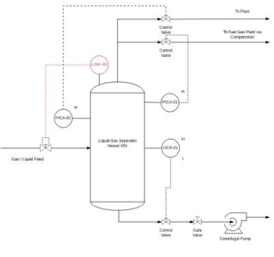
Figure 1 - simplified P&ID for a Liquid-Gas Separator Vessel
A Hazard and Operability has been carried out on the current design intent of the Liquid-Gas Separator Vessel system and the potential liquid overfilling of the vessel has been identified as a credible hazard scenario, for the assignment the scenario to consider is that hydrocarbon liquid enters the fuel gas plant line, with the potential of loss of containment due to liquid entering the compressor train and escaping.
The loss of containment is estimated as a potential flange failure with a release rate of 50 kg/s, which, on ignition, will lead to a jet fire with the potential loss of life of a single field operator. The operators work a 12-hour shift and spend approximately 2 hours per shift in the compressor train area.
As liquid entering the flare line would be captured in the Flare Knock Drum, it is not required to further evaluate this scenario at this time.
The following causes of a higher liquid level have been taken from HAZOP:
Cause 1:Level sensor fails low (LICA-01), causing the valve to close when required open, leading to increased liquid level.
Cause 2: Gate valve left closed due to operator error, not correctly following a short procedure, following the isolation of the pump for routine maintenance. The pump maintenance routine frequency is every 3 years
a)Based on the design intent. Complete the LOPA summary template provided in Table 1 for each of the two identified causes. Determine the target Safety Integrity Level (SIL) and Risk Reduction Factor (RRF) for the SIF (LZHL-01) using the data provided above and any additional data you require taken from recognised sources such as CCPS, UK HSE, CDOIF and the Module CPE6280 material. Fully explain, reference and justify your assumptions when using the data you have chosen and show any calculations you may have made. (10 Marks)
b)The current design intent for the SIF LZHL-01 is based on a "1oo1" single channel architecture based on the following type of equipment:
Sensor Sub System:
Vibrating Fork Level Switch with smart functionality with diagnostics (For example, E&H, Vega, etc)
Logic Solver Subsystem:
Safe PLC with diagnostics including Input & Output cards (For example Siemens, Rockwell, HIMA, Yokogawa etc)
Final Element Sub System:
Quarter Turn Ball valve with spring return actuator (air fail closed) and electrical solenoid, no diagnostics (For example Emerson, Maxseal, Worcester, Cameron, etc)
Draw a system block diagram of the SIF, identifying each of the components in the SIF, to which subsystem it has been allocated and the interconnections between the components.
State the mode of operation of the SIF
Develop a Reliability Block Diagram (RBD) for your chosen SIF architecture.
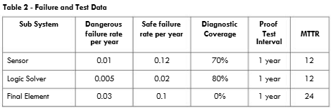
Using the data in Table 2, calculate the probability of failure on demand average (PFDavg) and spurious trip rate for each of the sub-systems and the overall SIF. Assume an auto diagnostic test interval of 100 milliseconds for the sensor and logic solver sub-systems (10 marks)

c) Research typical vendor failure data for the example vendor equipment in 1b, compare the vendor failure data against the data in table 2, which data is more conservative. By repeating the calculations, demonstrate what the impact would be on the achieved PFDavg. (10 marks)
d) Compare the calculated PFDavg in 1b to the target PFDavg taken from the LOPA in question 1a. State if the target PFDavg has been achieved. Assuming the PFDavg has not been achieved, examine the RBD for each of the sub-systems to determine how the overall PFDavg can be improved. Propose changes to the SIF architecture that will be required, and develop a new RBD for your chosen SIF architecture and recalculate to demonstrate the PFDavg reduction. (10 Marks)
A safety study of the pipeline and upstream process has identified that it is feasible to generate a high pressure in the system upstream of the Liquid-Gas Separator Vessel V01.
The project team has decided to implement a SIL3-capable high-pressure protection system (HIPPS) upstream of the Liquid-Gas Separator Vessel V01.
A fault tree study for the overpressure scenario has been completed, and the target PFDavg for the HIPPS SIF has been selected as PFDavg = 0.0002.
The pipeline safety study has identified the Process Safety Time for the hazard scenario as 20 seconds and proposes that the response time for the SIF be 70% of that time.
For the assignment, assume the diameter of the pipeline is 300mm.
Assuming a low demand mode of operation, you are required to carry out market research to identify components that comply with IEC 61508 and, using the component safety manual, obtain the necessary data for you to develop the architecture for the SIF.
Base the design of the SIF on the following type of equipment:
Sensor Sub System:
Based on a Pressure Transmitter with smart functionality with diagnostics
Logic Solver Subsystem:
Solid State with diagnostics
Final Element Sub System:
Quarter Turn Ball valve with spring return actuator (air fail closed) and electrical solenoid, no diagnostics.
Required hardware fault tolerance for a SIL3 capable system based on the appropriate IEC 61508-2 Hardware fault Tolerance Tables
The estimated response time of the device
Note: If the Valve vendor data does not include an estimated response time, you may assume 25mm per second for this assignment
a)Propose a hardware architecture that you assume will meet the SIL 3 target in terms of hardware fault tolerance, Systematic Capability and achieve the target PFDavg of 0.0002 and draw a system block diagram of the SIF identifying each of the components in the SIF, to which sub system it has been allocated and the interconnections between the components. (5 Marks)
b)Calculate the overall response time for the SIF architecture and compare it to the proposed overall SIF response time of 70% of the Process safety time, and state if the response time is achieved (5 Marks)
c)For your chosen SIF architecture, using the data from your market research of your chosen components, calculate the probability of failure on demand average (PFDavg) for each of the sub-systems and the overall SIF Ensure that you account for common cause failures within the SIF architecture (5 marks)
d)Compare the calculated PFDavg to the target PFDavg of 0.0002. State if the following targets have been achieved for the SIF:
If any of the targets have not been achieved, propose changes to the SIF components or architecture that will be required to achieve this requirement. (5 Marks)
The project team has accepted the proposed HIPPS architecture, but before it can be implemented, you are required to carry out a Security risk assessment, based on UK HSE guidance OG-0086.
Base the risk assessment on the system block diagram developed for the SIF in question 2a, with the addition of:
Using the data collected for question 2 and taking any additional data required from the Module CPE6280 course material and fully explain, reference and justify your assumptions.
a) Complete a simple asset register for the HIPPS system components, completing the IACS device risk level after you have completed the risk assessment. (5 Marks)
b) Select the threats, threat agents, vulnerabilities, safeguards and consequences you consider most appropriate to your system design and carry out the security risk assessment (5 Marks)
c) Based on the selected IACS device risk levels, draw appropriate zones and conduits onto the HIPPS system
Take our academic assistance & get 100% plagiarism-free papers
Buy Today, Contact UsThe project team has accepted the proposed HIPPS solution, and the project is due to kick off. Based on the guidance in IEC 61511-1 Clause 6 and Clause 17, develop a Functional Safety Management Plan (FSMP) for the SIS safety lifecycle and carry out a management of change impact analysis.
a)For the FSMP, populate the Inputs and Outputs with titles of the documentary evidence you will be expecting to be provided to ensure that the verification will be fit for purpose for each of the lifecycle phases. (10 Marks)
b)For the Impact analysis, complete the analysis summarising the outcome and any recommendations. Include in the analysis the hazards/hardware/software you consider to be potentially impacted by the change, and include the titles of the documentary evidence that will support your analysis outcome. (10 Marks)
Stuck on your CPE6280 Instrumented Systems & Functional Safety? Don't worry! Our Engineering Assignment Help service is the best for you. If you need help with assignments, our expert PhD writers will provide you with original content. And yes, you will also get free assignment samples, which will give you a perfect idea of how to write a top-quality assignment. Don't worry about the deadline, as we guarantee on-time delivery. Contact us now for high-quality and plagiarism-free work and boost your grades!
Hire Assignment Helper Today!
Let's Book Your Work with Our Expert and Get High-Quality Content
