CIVL3170 Administration guidance
The workload required for this assignment is substantial and perhaps underappreciated at first glance.
- Therefore, you should start each stage of this assessment as soon as you have the required information (from lectures, tutorials, readings, etc.).
- Your assessment must be bound with a University of Newcastle group-work cover sheet.
- Submitted work must be completed on 5 mm grid engineering calculation paper, including all calculations and drawings. An example of suitable engineering paper is shown on the last page of this brief.
- You are required to complete this assessment in groups of 2. The main function of this assessment is to provide you with an opportunity to learn some of the required design skills that will help with the Final Exam. Therefore, while it is good practice to divide the tasks in this assessment between your group, you should ensure that you fully understand every section, including the ones calculated by your partner.
- Hence, it’s recommended that you adopt a two-stage process for every section of your calculations; that is, if one person does a section of the calculations, then the other person thoroughly checks these calculations. Moreover, as both group members are equally accountable for all the submitted work, this process will help improve your mark.
Overview of CIVL3170
In this assignment, you will determine the ultimate strength design loads for a proposed warehouse in Geraldton, WA. The warehouse is proposed to be of steel portal frame design with dimensions as per Section 2, to suit the client’s needs. The design loads you determine are to be in accordance with AS1170 and are required for the first internal portal frame (Figure 1) and the middle mullion located on the Western end wall (Figure 1).
It is strongly recommended that you complete the relevant design calculations with constant reference to this document, including the assumptions and guidance sections. 2. Building layout The proposed warehouse is of steel portal frame design. The building plan and elevation for the warehouse are shown in Figure 1 and Figure 2 respectively. The Eastern wall has two main openings for roller doors. The Southern wall has a service door with dimensions 3 m x 2.5 m. Variables for the warehouse are given in Table 1. Figure 3 shows the wind direction notation for theta used in this assignment.

")
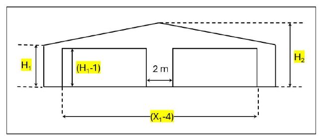
Figure 2. Eastern elevation of warehouse (drawing not to scale)

Figure 3. Wind direction notation for theta
CIVL3170 Assessment Requirements (as per the marking rubric):
Preliminary points:
- You are to register your group of two via Canvas, then work in this group to determine the ultimate-strength design actions for the warehouse described in Section 2.
- Your calculations are to be in accordance with AS1170.0-2011, AS1170.1-2009 and AS1170.2-2021. If superseded versions of the standards are used, you will encounter a 50% penalty on your mark. The most up-to-date standards can be obtained via The University of Newcastle’s library webpage through the ‘database’ portal and then by clicking on ‘Australian Standards’. If you haven't already, you will need to make an account with SAI Global.
Primary assessment requirements:
(a) Task:
Calculate design wind speed and determine wind pressure coefficients for all unique cases including:
- The wind speed for each orthogonal direction as shown in Figure 3.
- The internal and external pressure coefficients of both the first internal portal frame and the mullion
- Label each wind load case for the frame as WL1, WL2, WL3, etc., and, o Label each wind load case for the mullion as ML1, ML2, ML3, etc.
Guide: Use the following notes to assist in the providing the required results: First calculate the design wind speed for each orthogonal / wind direction.
- You will need to check three different opening configurations for the roller doors i.e. both doors open, both doors closed, one door open/one door closed.
- You must calculate the internal and external pressure coefficients individually for each orthogonal / wind direction (=0o, =90o, =180o, =270o).
- For each unique wind load case you must show the external pressure coefficients on a sketch of the building plan.
- As there will many wind load cases that you will define in section 3(a), you should annotate any duplicate WL case with a reference back to where it was first drawn, e.g. "same as WL5."
- An example of resulting wind load case diagrams for the portal frame and mullion is shown in Figure 6
Assumptions: you must assume the following:
- The service door is always open
- The building is exposed to conditions consistent with Terrain category 2.5 except on the North side of the structure. On the North side of the structure only, there is multiple buildings and trees visible, typically of a height less than the building height.
- There are no other adjacent buildings near the warehouse with a height greater or equal to the warehouse height. Further, there are no hills, ridges or escarpments near the structure.
- The cladding on all walls is not permeable.
- The warehouse has a design life of 50 years.
- Assume a shielding parameter (s) = 1.5 for wind directions N, NE and NW.
(b) Task:
Write down the pressure coefficient combinations – from Section 3(a) – which you consider are "critical”:
- Include each wind load case in equation form only with relevant ULS load combinations (e.g., 1.2G+1.5Q, 1.2G+WL2, etc.,)
- Describe the reason for selecting each critical load combination briefly.
- (Hint: will probably be less than 10 critical load cases)
Guide: Use the following notes to assist in the providing the required results:
- List the critical load combinations and provide an explanation of why they would be considered critical for design.
- Consider multiple variations (including multiple wind loads cases) and justify. Assumptions: Consider the following critical load combinations for the listed portal frame ONLY:
- uplift vertical loads (rafter)
- downward vertical loads (rafter)
- max. horizontal loads (sway, columns)
- combinations of vertical and horizontal loads.
(c) Task:
Present loading diagrams for both the first internal portal frame and for the mullion including the following four load cases ONLY:
- 1.2G + 1.5Q
- =0o (worst case Wu for right side of portal frame)
- =90o (worst case Wu for rafter)
- = 180o (worst case Wu for left side of portal frame)
 Get Expert-crafted assignments


