| Category | Assignment | Subject | Engineering |
|---|---|---|---|
| University | University of Hertfordshire | Module Title | 5FTC2200 Civil Engineering Structural Design |
Modules may have several components of assessment and may require a pass in all elements. For further details, please consult the relevant Module Handbook (available on StudyNet/Canvas, under Module Information) or ask the Module Leader.
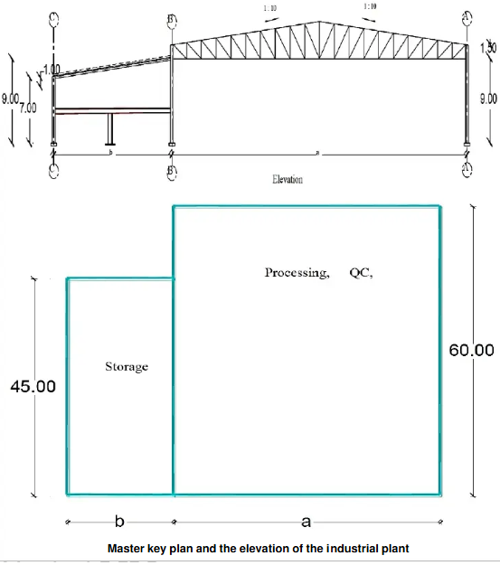
An industrial plant is planned for construction in Sadat City, Alexandria, Egypt, as part of a strategic development project. The plant will consist of several steel structures, including the Processing, Engineering, and QC Building. These facilities are essential for supporting the industrial processes, engineering operations, and quality control activities of the plant.

The class has been organised into groups according to Table 1 I've attached. Each group has been assigned a specific building footprint and corresponding building dimensions to work on. These assignments are intended to simulate real-world engineering challenges, encouraging collaboration and practical application of structural engineering concepts.
Each group will utilise the building footprint and dimensions provided in the attached table-2 to develop their designs, ensuring alignment with the project requirements and applicable standards.
Do You Need 5FTC2200 Assignment for This Question
Order Non-Plagiarised AssignmentAll systems shall be designed according to the following engineering data:
It is required to:
Prepare a detailed AutoCAD drawing (Scale 1:100) to a convenient scale, illustrating a general layout of all steel buildings in the industrial plant. The drawing should include the following elements:
Calculate all loads acting on the building's steel structural elements, including dead loads, live loads, and wind loads. Provide sketches showing load distribution on the cross section, as well as wind load effects on the roof and columns. Ensure all calculations follow relevant design codes and include labelled sketches for clarity.
Use SAP 2000 software to analyse the steel truss under the load conditions calculated in Task 2. Model the truss structure, applying the calculated dead, live, and wind loads, and define appropriate load combinations according to ECP. Run the analysis to obtain the internal forces (tension and compression) in each truss member. Calculate the ultimate loads (compression and tension) in the truss members based on the SAP2000 results.
Design all tension and compression members of the steel truss based on the ultimate loads calculated in Task 3. Select suitable steel sections for tension and compression members, ensuring they meet ECP code requirements. Provide detailed calculations, annotated sketches showing designed member sizes, and a summary comparing member capacities to the calculated forces. (minimum four members)
Provide a detailed design and calculation for all truss joints, including forces at each joint and the selection of appropriate connection types (bolted). Include calculations for bolt size, spacing, and verify joint strength under the applied forces. Provide scaled drawings (1:10) for all joints, detailing bolt arrangements, and gusset plate dimensions, along with a summary report of the designs and compliance checks.
Design the columns on axes A and B to resist the ultTask 7imate normal forces obtained from the numerical analysis in Task 3.
Create a 3D model of the steel structure in SAP2000, including all beams, columns, trusses, and the mezzanine floor, based on the provided building dimensions.
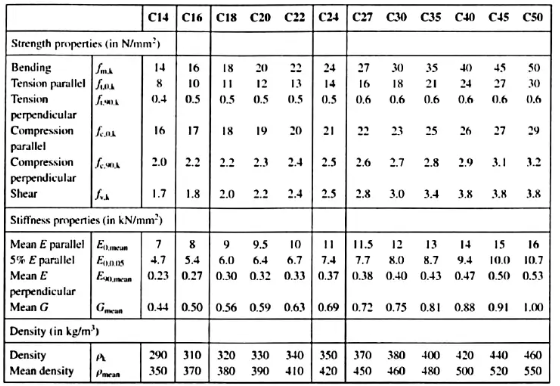
A planned softwood beam of C20 is 100 mm wide x 250 mm deep, has an effective span of L = 5.00 m and carries the following unfactored loads:
The beam is part of the ground floor of an office building and is laterally restrained by the flooring boards (considered as a simply supported beam). Check whether its bending strength at ULS is adequate (Eurocode 5).

**** The grading breakdown will be as follows:
Drawings must be printed on A3/A2 paper, using AutoCAD, and should include layout and connection details. Additionally, prepare a poster comprising a general layout, connection details, and a 3D-SAP numerical model.
Hire Experts to solve this assignment before your Deadline
Buy Today, Contact Us1. All SAP2000 files used for analysis, including (S2k) files.
2. AutoCAD files containing detailed drawings (save as V. 2018).
3. Printed drawings on A3/A2 sheets at an appropriate scale.
4- Please carefully read the report requirements within the brief.
5- You must submit your professional report in a .docx or .doc file with all the model files attached.
6- Your SRN (Student Registration Number) must be in the first line of your report.
Ensure that all submissions meet the specified standards for clarity, accuracy, and professional presentation.
Write an MS Word report including all the required steps above with the following:
Do you need help with an assignment for 5FTC2200 Civil Engineering Structural Design? Look no further! We are here for civil engineering assignment help. We also provide free assignment solutions written by PhD expert writers—100% original content, no plagiarism! Plus, we also provide assignment help, that too by complete it before the deadline. Quality and accuracy are taken care of completely. So contact us today and be stress-free!
Hire Assignment Helper Today!
Let's Book Your Work with Our Expert and Get High-Quality Content
