| Category | Assignment | Subject | Engineering |
|---|---|---|---|
| University | RMIT University | Module Title | OENG1189 Topology Optimization and 3D Printing |
| Assessment Title | Assignment 1 |
|---|---|
| Academic Year | 2025 |
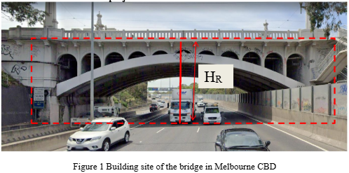
This is an individual task for each student. You are required to conduct a structural optimisation design on a bridge structure using Abaqus to simulate its behaviour. This bridge is supposed to replace an existing Church St Bridge on church St, Melbourne VIC 3141 as shown in Figure 1. Google map coordinates: -37.83384, 144.99664.
You should measure the size of the bridge sites using images you snap-shot on google map. You should use the two red lines in Figure 1 as the scale reference. To personalise the assignment, the height, HR, of the red line on the right side in Figure 1 is 6.00m + the last two digits of your student number, i.e. if you student number is s3543485, then the length of the red line is 6.85m. Please indicate the possible errors in your measurement. You will measure other sizes (i.e. length, width) of the bridge using this size as a reference.
You should follow the optimisation design cycle as illustrated in lecture 1 (or lecture 4 in detail) to do your design. Generally, you will follow two routes. In the first route, you will act as an optimizer with the ESO principle and remove inefficient materials-i.e. regions with lower stress levels. You will get an optimal design manually with at least 3 iterations. The second route is to use the MATLAB code with proper input parameters to get an optimal design. Some detailed guidance and requirements are listed in the following sections.
You should determine the approximate sizes of the design space (usually larger than the size of the existing bridge) to be optimised. You should consider the following factors:
An example of the acceptable design region is illustrated in Figure 2, and this design domain is used in the MATLAB code provided in Assignment 1.
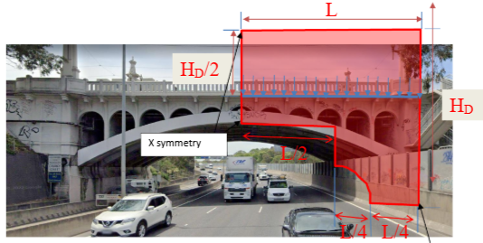
Figure 2. Example of an acceptable design domain for the bridge
You are required to design a bridge with an optimal stiffness using concrete. This design is supposed to be constructed by a 3D construction printer. The concrete material has a Young’s modulus of 40GPa and Poisson’s ratio of 0.26. The compressive strength of the fully cured concrete is 40MPa, and the tensile strength is 4MPa. The critical load for validation of your simplified Finite Element Model (FEM) can be considered as a total load of 800kN in the bridge with a maximum deflection of less than 1/250 of the length of the bridge and around 0.3mm.
You are expected to demonstrate the completion and accuracy of the optimisation design in your report. Some detailed guidance and requirements are listed in the following sections.
2.3.1 Expected results from optimisation design
For the manual optimization with ESO, you will provide the following information:
For the optimisation with MATLAB code, you will provide the following information:
You should compare the finite element results from different designs and finalise different innovative designs. For each innovative design, you should provide
2.3.2 Expected work from finite element analysis
You are expected to use Abaqus to check the performance of your design through the following steps
2.3.3 Detailed results from finite element analysis
The following results from finite element analysis using Abaqus should be included in your report:
In your report, you should provide evidence (Screen shots of contour plot from Abaqus or MATLAB, table for data input, sketch, charts etc) to show the completion of the following required tasks for Project 1:
(It is acceptable to do those tasks through 2D FEM with a topology of the existing bridge if you started your assignment from week 2)
The total mark for this assignment 1 is 30 marks. There will be 5 criteria to mark this assignment.
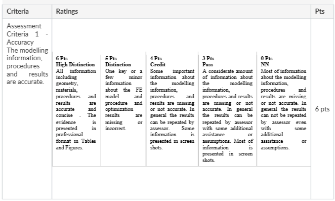
Criteria 1 – Accuracy. The modelling information, procedures and results are accurate.
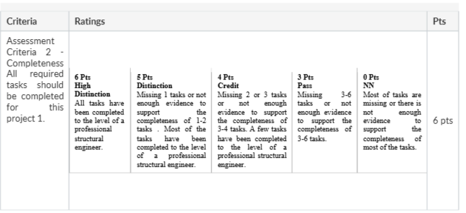
Criteria 2 – Completeness. All required tasks should be completed for this project 1.
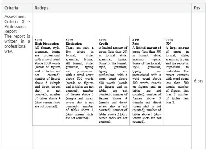
Criteria 3 – Professional Report. The report is written professionally.
Criteria 4 – Innovative. The final optimal structures obtained should be innovative.
Criteria 5 – Presentation. A clear video report to illustrate the overall project and its outcomes.
More detailed information to earn marks can be found in the detailed marking rubrics as attached at the end of this assignment illustration.
Late submission of this assignment will incur a penalty of 5% of the total mark of this assignment for each day after the due date.
Achieve Higher Grades with OENG1189 Assignment Solutions
Order Non-Plagiarized AssignmentAre you having trouble completing your OENG1189 Topology Optimization and 3D Printing? Our Mechanical Engineering Assignment Help service is the best for you. You can even check our free assignment samples before placing your order. We promise on-time delivery and 24/7 support, no matter your academic needs. From Business Management to technical subjects, we cover it all. We also provide Southern Cross University Assignment Samples that have been written by the phd expert writers. Contact us now!
Hire Assignment Helper Today!
Let's Book Your Work with Our Expert and Get High-Quality Content
