| Category | Assignment | Subject | Engineering |
|---|---|---|---|
| University | Nanyang Technological University | Module Title | Electronics Engineering |
(i) Find the node voltages v1, v2, v3 in the circuit given in Figure Q1. (12 marks)
(ii) Find the power absorbed/delivered by the dependent current source. (3 marks)
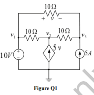
Figure Q1
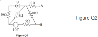
(i) Find Thevenin’s equivalent between the nodes A and B in the circuit given in Figure Q2. (12 marks)
(ii) Determine the maximum power that can be drawn from the circuit by connecting a resistor between nodes A and B. (3 marks)
The switch S in the circuit shown in Figure Q3 was open for a long time before being closed at t=0. Find the expression for the capacitor voltage, vc(t), after the switch is closed.
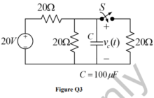
Figure Q3 (10 marks)
Using the Superposition principle, find the current I in the circuit shown in Figure Q4.
Do You Need an Assignment for This Question
Order Non-Plagiarised Assignment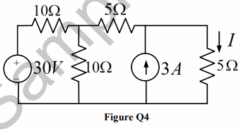
Figure Q4 (10 marks)
The load shown in Figure Q5 is connected to a 220 V, 50 Hz source. [R= 100Ω, L= 0.01 H and C= 500 μF].

Figure Q5
(i) Find the equivalent impedance of the load. (5 marks)
(ii) Find the RMS current through each branch and their phases concerning the source voltage. (4 marks)
(iii) Find the source current (RMS) and its phase concerning the source voltage. (4 marks)
A practical coil modelled as Zcoil = Rc + jxl is connected in series with a purely resistive element R = 40 Ω. An AC source of 220 V, 50 Hz is connected across the series circuit. The RMS voltage measured across R is 90 V, and measured across Zcoil is 140 V.
(i) Find the RMS current through the circuit. (2 marks)
(ii) Considering the current phasor as I∠0°, sketch the phasors of the voltage across R, the voltage across Zcoil, and the voltage across the total load. (5 marks)
(iii) Using the phasor diagram of part (b) or using any other method, find the values of Rc and XL. (5 marks)
In the circuit shown in Figure Q7, the transformer turns ratio is N1: N2 = 5:1. The supply voltage is 240 V, 50 Hz. The components are R1 = 10 Ω, R2 = 10 Ω, and Z = j10 Ω. Determine the primary current and the secondary voltage.
Achieve Higher Grades with Assignment Solutions
Buy Today, Contact Us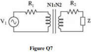
Figure Q7 (12 marks)
You have to design a DC power supply to provide 1 A to a 12 Ω load. The mains power supply is 240 V, 50 Hz AC. It is desired to have voltage ripple of less than 1% of the load voltage. Assume all components used are ideal.
(i) Draw the circuit schematic if a half-wave rectifier is used. Label all components properly. (3 marks)
(ii) What is the required turns ratio of the transformer? (2 marks)
(iii) Determine the value of the smoothing capacitor required to meet the specification of ripple. (5 marks)
(iv) Sketch the waveform of the voltage across the diode. (3 marks)
Do you need help with an assignment for Electronics Engineering? Look no further! We are here for electronics engineering assignment help. We also provide free assignment solutions written by PhD expert writers—100% original content, no plagiarism! Plus, we also provide assignment help, that too by complete before the deadline. Quality and accuracy are taken care of completely. So contact us today and be stress-free!
If you want to see the related solution of this brief then click here:- Engineering
Hire Assignment Helper Today!
Let's Book Your Work with Our Expert and Get High-Quality Content
